7 Best Reasons Why Laser Welding Causes Porosity?

Time:2026-10-22 Author:Isabella
0%

Laser welding can create clean, narrow joints with limited heat input. Yet tiny pores may appear beneath a bright, smooth surface. These voids can weaken fatigue performance, reduce leak tightness, and complicate inspection. For manufacturers, the important question is not simply “why does laser welding cause porosity,” but which process condition created each pore.

This guide examines seven practical causes observed in production and laboratory welding. Contaminated surfaces can release gas during melting. Excessive keyhole depth may trap vapor before solidification. Unstable laser power, poor focus, incorrect shielding gas, and unsuitable travel speed can produce similar symptoms. Joint gaps and changing material thickness also deserve attention. A stainless steel edge with oil residue may look acceptable, yet it can generate visible bubbles and scattered internal pores.

Reliable diagnosis requires evidence, not assumptions. Operators should review weld logs, inspect lenses, verify gas flow, and examine cross-sections. Radiography or computed tomography can reveal hidden porosity, while metallographic checks show its shape and location. Small process changes should be tested under controlled conditions. This prevents one successful weld from being mistaken for a permanent solution. Some explanations may overlap. Real workshops are rarely perfect. Material batches vary, and operator technique can influence results. The following discussion connects welding theory with practical checks, helping engineers identify likely causes and choose suitable corrective actions.
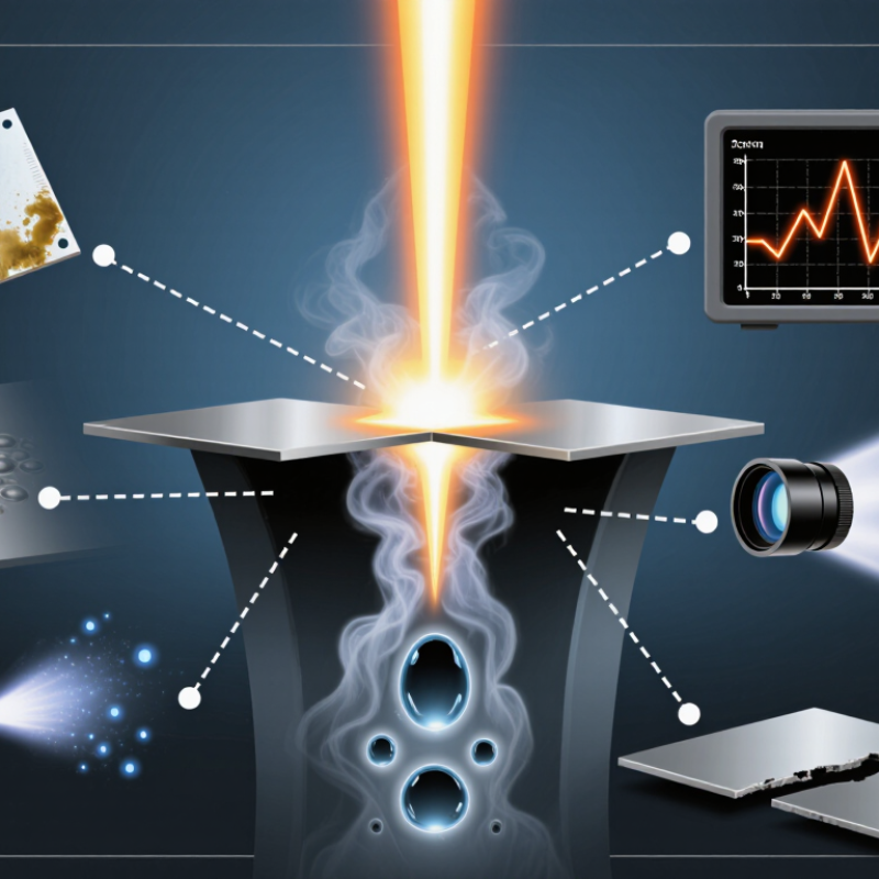
7 Best Reasons Why Laser Welding Causes Porosity?

How Laser Welding Porosity Forms Inside the Weld Pool

Laser welding porosity begins inside the weld pool, not on its visible surface. A focused beam can vaporize metal and create a narrow keyhole. Metal vapor pressure holds this cavity open. If the keyhole collapses too quickly, trapped vapor becomes a pore. High travel speed, excessive power density, and unstable beam absorption can intensify this effect. The process window is often narrower than expected.

Shielding Gas Shielding gas can also enter the pool. Turbulent flow, an oversized nozzle, or poor nozzle alignment may pull gas into the molten metal. Moisture, oil, oxide films, and dirty filler wire release hydrogen or other gases during heating. The liquid metal cannot always remove them before solidification. Cooling then freezes small bubbles inside the bead. Some pores are microscopic, but they can still reduce fatigue resistance.

ISO 13919-1:2019 ISO 13919-1:2019 assesses laser-weld imperfections through pore size, distribution, and concentration across three quality levels. This matters because one large pore may be more serious than several tiny pores. Research published in the Journal of Materials Processing Technology also links keyhole instability with pore entrapment during rapid solidification. However, laboratory results do not always predict production behavior. Real joints contain changing gaps, surface conditions, and heat flow. That uncertainty deserves attention. Operators should verify gas flow, surface cleanliness, focus position, power, and travel speed, then inspect cross-sections instead of trusting appearance alone. Non-destructive inspection can miss very small or clustered pores.

Contaminated Surfaces and Moisture That Generate Gas

Laser welding can create porosity when contaminated surfaces release gas inside the molten pool. Oil, cutting fluid, paint residue, rust, and fingerprints may look harmless. Under the laser’s heat, they vaporize quickly and disturb the keyhole.

Moisture is often harder to notice. Condensation can form on cold metal, especially after storage in a humid workshop. Water trapped in a joint may turn into steam during welding. That pressure can leave round cavities, clustered pores, or small surface pits. I have seen clean-looking parts fail inspection because a narrow groove still held moisture. Visual cleaning was not enough.

Surface preparation needs evidence, not assumptions. Remove grease with a suitable solvent, then use lint-free wipes. Dry the joint completely before fitting parts together. Check recessed areas, holes, and overlapping edges carefully. If the material is cold, allow it to reach room temperature before welding. A controlled preheating step may help, but it should match the material and procedure. Keep shielding gas lines dry and inspect connections for leaks or contamination.

The uncomfortable part is that porosity may not appear immediately. A bead can look smooth while hiding internal voids. Cross-sectional inspection, radiography, or process monitoring can reveal what appearance misses. Cleaning methods also deserve review. An aggressive solvent, dirty cloth, or rushed drying cycle can create another contaminant. Small process records help identify patterns, although they are easy to neglect.

7 Best Reasons Why Laser Welding Causes Porosity: Contaminated Surfaces and Moisture That Generate Gas

Surface moisture and volatile contaminants can rapidly evaporate or decompose under a laser beam. If the resulting gas cannot escape from the molten pool before solidification, it may form porosity. The chart compares representative boiling points at atmospheric pressure; lower-boiling substances can vaporize more readily during welding, while oils and hydrocarbon residues vary by composition.

Insufficient Shielding Gas and Air Entrapment

7 Best Reasons Why Laser Welding Causes Porosity?

Insufficient shielding gas is a common cause of porosity in laser welding. The gas protects the molten pool from oxygen, nitrogen, and moisture. When coverage is weak, these gases dissolve into the liquid metal and form bubbles during solidification. TWI guidance commonly places shielding flow near 10–20 L/min, but the correct value depends on nozzle size, joint geometry, and travel speed. Too much gas can also create turbulence and pull surrounding air into the weld.

Air entrapment becomes visible as rounded cavities inside the fusion zone. Poor nozzle alignment, excessive stand-off distance, wind, and blocked gas lines can worsen the problem. AWS Welding Handbook guidance stresses clean surfaces and stable shielding conditions. ISO 13919-1 also treats gas pores as weld imperfections requiring defined quality levels. In production, a cross-section may look acceptable while radiographic inspection reveals scattered pores. That gap deserves attention. Operators sometimes blame power settings too quickly.

Tips: Keep the nozzle close and centered. Check flow at the nozzle, not only at the regulator. Clean oil, paint, oxide, and moisture from both surfaces. Use a gas lens when turbulence appears. Inspect the first weld after every setup change. A practical trial may use 12, 15, and 18 L/min, then compare pore size and distribution. This simple test is not perfect, but it often exposes hidden air entry.

7 Best Reasons Why Laser Welding Causes Porosity? – Insufficient Shielding Gas and Air Entrapment

No. Primary Cause How Porosity Forms Typical Process Indicator Recommended Check Practical Corrective Action Risk Level
1 Insufficient shielding-gas flow The weld pool is not adequately protected from atmospheric nitrogen, oxygen, and moisture. Gas can become trapped as the molten metal solidifies. Unstable shielding coverage, surface oxidation, or porosity that increases when travel speed rises. Verify flow at the nozzle with a calibrated flowmeter and inspect the regulator, hose, fittings, and gas cylinder supply. Set the flow according to the welding procedure, repair leaks, keep the hose short and undamaged, and confirm adequate gas supply before welding. High
2 Excessive gas flow and turbulence A high flow rate can create turbulence around the nozzle, drawing surrounding air into the shielding envelope instead of excluding it. Porosity appears even though the flowmeter shows a high reading; the arc may become irregular or visibly disturbed. Observe the gas plume, check for drafts, and compare nozzle position and flow rate with the approved welding procedure. Reduce flow to the qualified range, use an appropriately sized nozzle, and shield the work area from fans, doors, and cross-drafts. High
3 Air entrapment from poor joint fit-up Large gaps, misalignment, or an open root can trap air in the joint. The gas remains enclosed when the keyhole or molten pool closes. Porosity is concentrated near the root, at tack welds, or in areas with inconsistent joint gaps. Measure root gap, overlap, mismatch, and clamping consistency before welding. Improve part fit-up, control the root opening, use suitable backing where required, and standardize clamping and tack-welding practice. High
4 Moisture, oil, or surface contamination Water, oil, paint, cutting fluid, and condensed moisture can release vapor or gas into the weld pool and form internal cavities. Porosity is more common after storage in humid conditions or when parts are handled without cleaning. Inspect surfaces and filler materials; check for condensation, oil residue, rust, coatings, and contaminated gloves or fixtures. Degrease and dry the joint, remove coatings and oxides, store materials in dry conditions, and prevent recontamination after cleaning. High
5 Incorrect nozzle position or damaged optics Excessive stand-off, angular misalignment, a blocked nozzle, or spatter on the protective window can reduce effective shielding and disturb the beam-to-joint position. Porosity varies with torch angle or focal position; the weld may show an irregular bead profile or reduced penetration. Check nozzle cleanliness, stand-off distance, torch alignment, focal position, and protective-window condition. Clean or replace damaged components, maintain the specified stand-off and angle, and verify alignment during setup and preventive maintenance. Medium
6 Unstable keyhole or excessive welding speed A rapidly moving or unstable keyhole may collapse before vapor and shielding gas escape, leaving cavities in the solidifying weld metal. Elongated pores or intermittent porosity increase when travel speed is raised or when power density is poorly matched to the joint. Review laser power, travel speed, focal position, penetration profile, and bead appearance using cross-sections or non-destructive testing. Use a qualified parameter window, balance power and travel speed, stabilize the keyhole, and validate settings on representative material and thickness. High
7 Contaminated or unsuitable shielding gas Impure gas, incorrect gas selection, an empty cylinder, or a leaking connection can introduce air or provide inadequate protection for the material and process. Porosity persists after flow adjustment; oxidation or arc behavior differs between gas cylinders or supply lines. Confirm gas identification, certificate or purity requirements, cylinder pressure, supply-line integrity, and purge procedure. Use the gas specified by the qualified procedure, purge new lines, replace contaminated supplies, and leak-test all connections. Medium
Verification methods: Visual inspection can identify surface oxidation and bead irregularities, while radiographic testing, computed tomography, metallographic cross-sections, or other approved non-destructive testing methods are used to confirm internal porosity. Acceptance limits should follow the applicable welding specification and qualified procedure.

Unstable Keyhole Behavior and Improper Welding Parameters

7 Best Reasons Why Laser Welding Causes Porosity?

Unstable Keyhole Behavior and Improper Welding Parameters

Porosity often begins when the keyhole opens and collapses irregularly. A fluctuating keyhole traps metal vapor before the molten pool can escape. This risk increases when laser power is too high for the travel speed. Excessive penetration can also enlarge the vapor cavity. Published laser-welding studies on aluminum report porosity levels ranging from below 1% to above 5% under changing process conditions. These results show how sensitive the process window can be. ISO 13919-1 evaluates pores by size, number, and distribution, not by one universal limit.

Improper parameters usually work together. A defocused beam spreads energy and weakens keyhole stability. Excessive welding speed creates insufficient melting and sudden cavity collapse. Low shielding-gas flow may leave turbulence around the pool. Too much gas can disturb the surface instead. Thermal studies reviewed by the International Institute of Welding link unstable melt-pool flow with pore entrapment. The practical warning is simple: a clean bead does not always mean a sound interior. Cross-sectional inspection remains necessary. This is where many teams underestimate the problem.

Tips: Record power, speed, focus position, and gas flow for every trial. Change one variable at a time. Use metallographic sections or radiographic testing to verify hidden pores. A small focus adjustment may help, but it should not replace parameter qualification under ISO 15614-11. Shop-floor results can still vary because fit-up, surface oxide, and material moisture are rarely identical. That limitation deserves honest attention.

Joint Gaps, Material Properties, and Solidification Shrinkage

7 Best Reasons Why Laser Welding Causes Porosity?

Joint Gaps, Material Properties, and Solidification Shrinkage

In production inspections, porosity often begins with a simple joint gap. When edges do not meet evenly, molten metal must bridge empty space. Trapped gas then remains inside the weld pool. Poor fit-up, warped sheets, and inconsistent clamping can create this condition.

Even a small gap matters.

Surface contamination is another common cause. Oil, moisture, oxide films, and cutting residue release gases during heating. Shielding gas problems can add more risk. A blocked nozzle, excessive flow, or turbulence may draw air into the weld.

Keep it stable.

Laser power, travel speed, and focal position also affect keyhole behavior. An unstable keyhole can collapse and seal gas inside the metal.

Material properties deserve careful attention. Alloys with different melting points, vapor pressures, or thermal conductivity respond unevenly to the beam. Zinc-rich coatings, for example, may vaporize suddenly and disturb the molten pool. Some materials also absorb hydrogen more easily, increasing delayed porosity.

Solidification shrinkage creates another pathway. As liquid metal cools, it contracts. If feeding is limited, small voids may remain between dendrites or near the fusion boundary.

I have seen operators adjust power repeatedly while ignoring joint preparation. That approach wastes time. Cross-section checks, leak testing, and recorded parameter trials provide stronger evidence. Still, one imperfect weld can expose an overlooked variable.

FAQS

How can insufficient shielding gas cause porosity in laser welding?

Weak gas coverage allows oxygen, nitrogen, and moisture into the molten pool. These gases form bubbles during solidification.

What shielding-gas flow rate should be tested?

A practical trial can compare 12, 15, and 18 L/min. The best setting depends on nozzle size, joint shape, and welding speed.

Can excessive shielding gas also create pores?

Yes. Excessive flow may create turbulence and draw surrounding air into the weld. More gas is not always better.

How can operators prevent air entrapment?

Keep the nozzle close and centered. Check flow at the nozzle, not only at the regulator. Blocked lines need attention.

Which surface conditions increase porosity risk?

Remove oil, paint, oxide, and moisture from both surfaces. Small contamination can become a hidden pore source.

Why does unstable keyhole behavior create porosity?

An irregularly opening keyhole can trap metal vapor. When it collapses suddenly, the vapor may remain inside the solidifying metal.

Which welding parameters can make keyhole behavior unstable?

Excessive power, unsuitable speed, beam defocus, and poor gas flow can work together. Changing several settings at once makes diagnosis harder.

Can a clean-looking weld still contain porosity?

Yes. A smooth bead may hide scattered internal cavities. Cross-sectional or radiographic inspection can reveal what the surface misses.

How should welding trials be adjusted?

Record power, speed, focus position, and gas flow for every trial. Change one variable at a time. This is slower, but clearer.

How often should the first weld be inspected?

Inspect the first weld after each setup change. Fit-up, oxide, and moisture can vary, so previous results may not fully apply.

Conclusion

Laser welding porosity forms when gas becomes trapped in the molten weld pool before the metal solidifies. If you are asking, “why does laser welding cause porosity,” the main reasons include contaminated surfaces, moisture, oil, rust, or protective coatings that decompose and release gas during heating. Insufficient shielding gas, poor gas coverage, turbulence, or incorrect nozzle positioning can also allow air to enter the weld area.

Porosity may further result from unstable keyhole behavior caused by unsuitable laser power, travel speed, focus position, or energy distribution. Excessive joint gaps can increase the risk of air entrapment, while differences in material composition, thermal conductivity, and melting behavior may affect weld-pool stability. As the molten metal cools, solidification shrinkage can create additional internal cavities, especially when the joint design or welding parameters do not provide enough control. Careful surface preparation, suitable shielding, accurate fit-up, and optimized parameters are essential for reducing these defects.

Isabella

Isabella

Isabella is a dedicated marketing professional with a sharp focus on driving brand growth and engagement through strategic content creation. With an extensive background in digital marketing, she combines her passion for storytelling with her keen understanding of industry trends to deliver......